How to Deploy Service To The ECS Fargate
-
 Chinthaka Dinadasa
 - 16 Jul, 2023
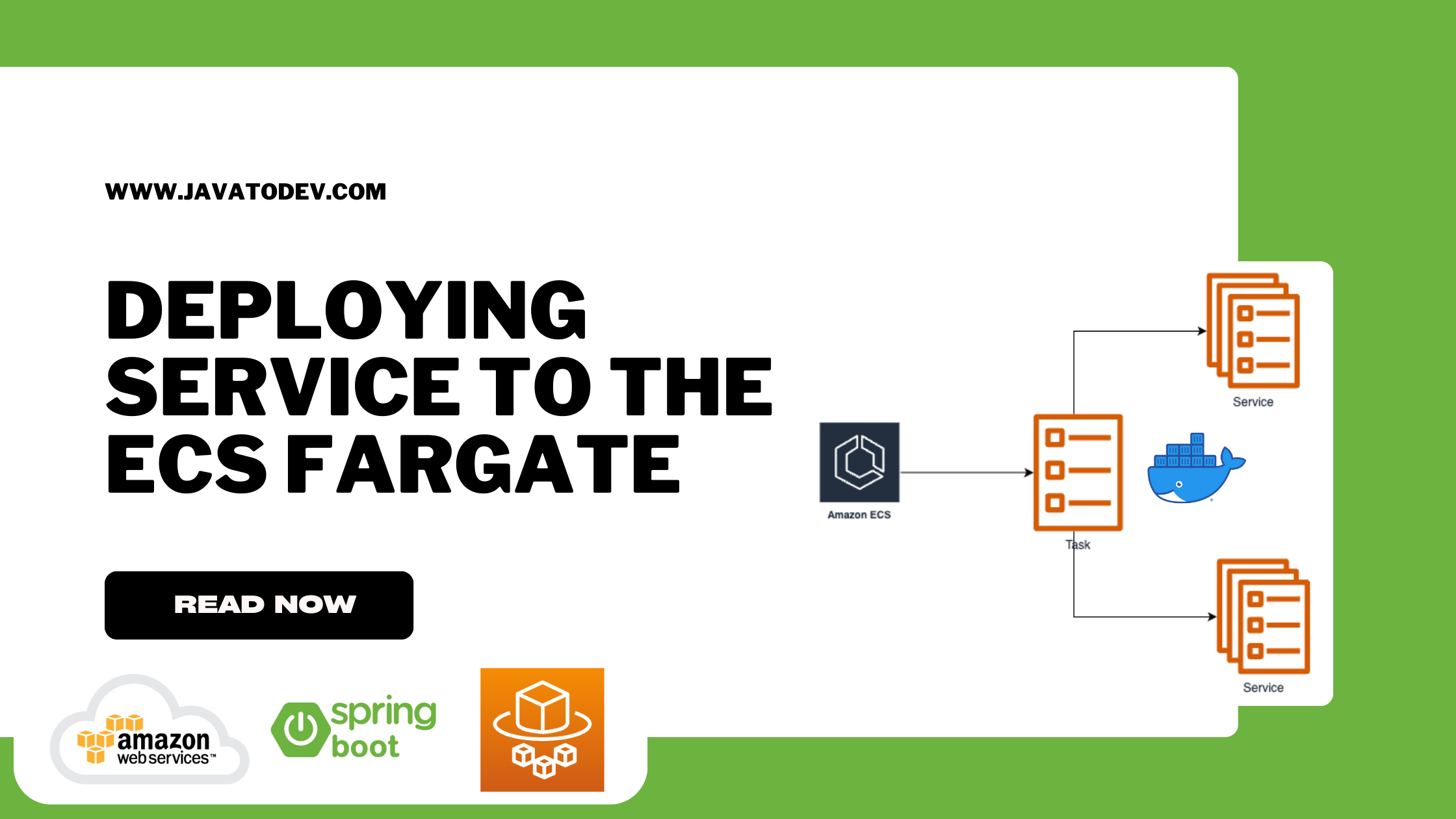
ECS Task Create Service, developers initiate the deployment for the created task definition.
Once the task definition is set up, ECS takes care of automatically creating and scaling the desired number of tasks based on the defined parameters.
This means that developers don’t have to manually provision and manage individual containers.
The tasks created by the Task Create Service are distributed across the available compute resources, such as EC2 instances or AWS Fargate.
This ensures efficient utilization of resources and optimized performance for the application.
Setting Up Environment
Here we can configure how the task distribution should be applied mainly with launch type and platform version.
Additionally, we can choose FARGATE or FARGATE SPOT for the capacity provider if we proceed with the capacity provider strategy.
Did you know you could save money in AWS by switching from Fargate to Fargate Spot? If you’re using ECS, Fargate Spot offers significant cost reductions by using spare capacity in the AWS cloud.
Fargate Spot, therefore, suits workloads that can tolerate interruptions. Good candidates might be websites or API servers since they’re normally processing short-lived requests.
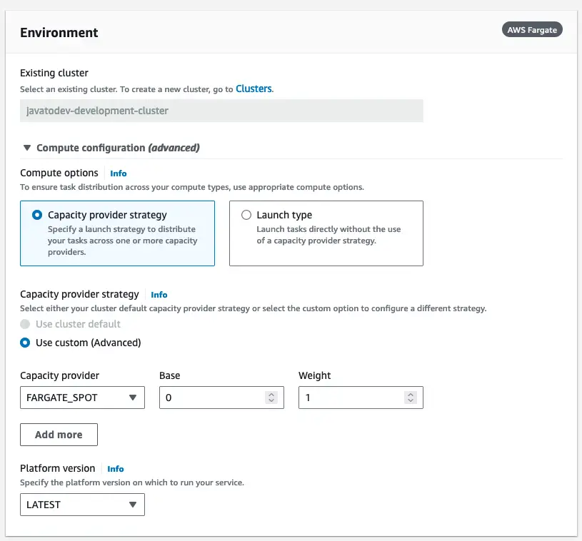
Fargate Compute configurations
After that, we should set the deployment configurations,
Inside this deployment configuration, we have to choose between application types from below,
-
Service - Launch a group of tasks handling long-running computing work that can be stopped and restarted. For example, a web application.
-
Task - Launch a standalone task that runs and terminates. For example, a batch job.
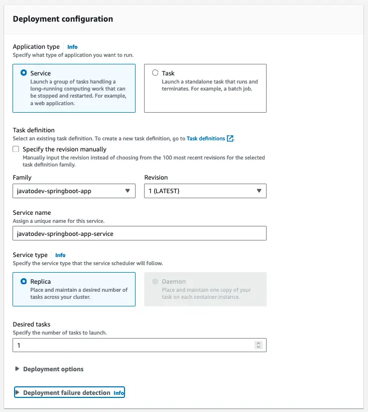
Deployment configuration with application type and service type configs
Networking Configurations
Here we can choose the VPC/Subnets with security groups that ECS service deployment use.
As per the architecture, we are going to deploy all the API containers under a private subnet.
Hence we have to choose only private subnets from the subnet selection after the VPC selection.
Most importantly, Here we have to choose the correct security groups that we have created for each component in this architecture. Here it should be ‘javatodev-ecs-app-fargate-sg’ as per the initial plan.
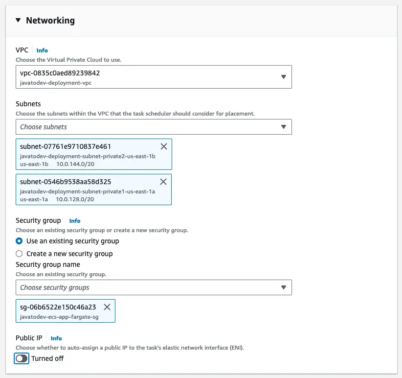
Networking configuration for the ECS fargate service
Load Balancing Configurations
With these configurations, we can expose our API deployed with ECS fargate via a public endpoint in a load-balanced infrastructure setup.
We have to choose an application load balancer that allows to load balance HTTP/HTTPS requests with path-based routing.
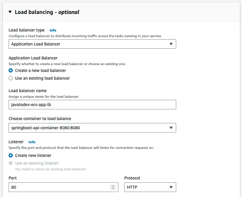
Load balancing configurations with load balancer type and listener configs
Target Groups
With this, we can configure the instances that should be registered under the load balancer.
Also, this configuration allows us to set up health checks for each instance that registers with the load balancer.
Since we have configured actuator endpoints on our original application source, we can define actuator health endpoints for health checks under the target group.
The health check grace period is the period of time (in seconds) that the Amazon ECS service scheduler ignores unhealthy Elastic Load Balancing health checks after a task has first started.
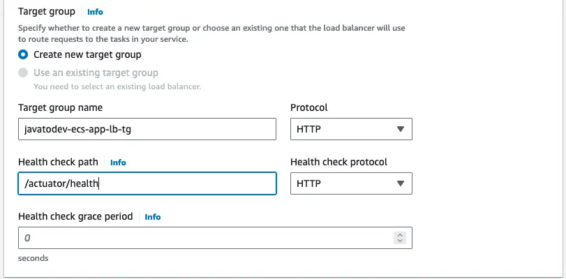
Setting target group with health check paths for a load balancer
All done, now we can proceed with placing our service for the deployment of this infrastructure.
But in the first attempt, the load balancer and service deployment will be failed due to the wrong subnet and security group settings. Let’s configure those correctly.
There is a manual configuration to change the subnet and security of this load balancer that we should change later.
This happens because this load balancer will be deployed on private subnets and the security group of the ECS service which we attached to the service definition.
In the first attempt you will get load balancer listeners notifying the component are Not Reachable even though there are services up and running inside the cluster as per the logs. Let’s fix this.
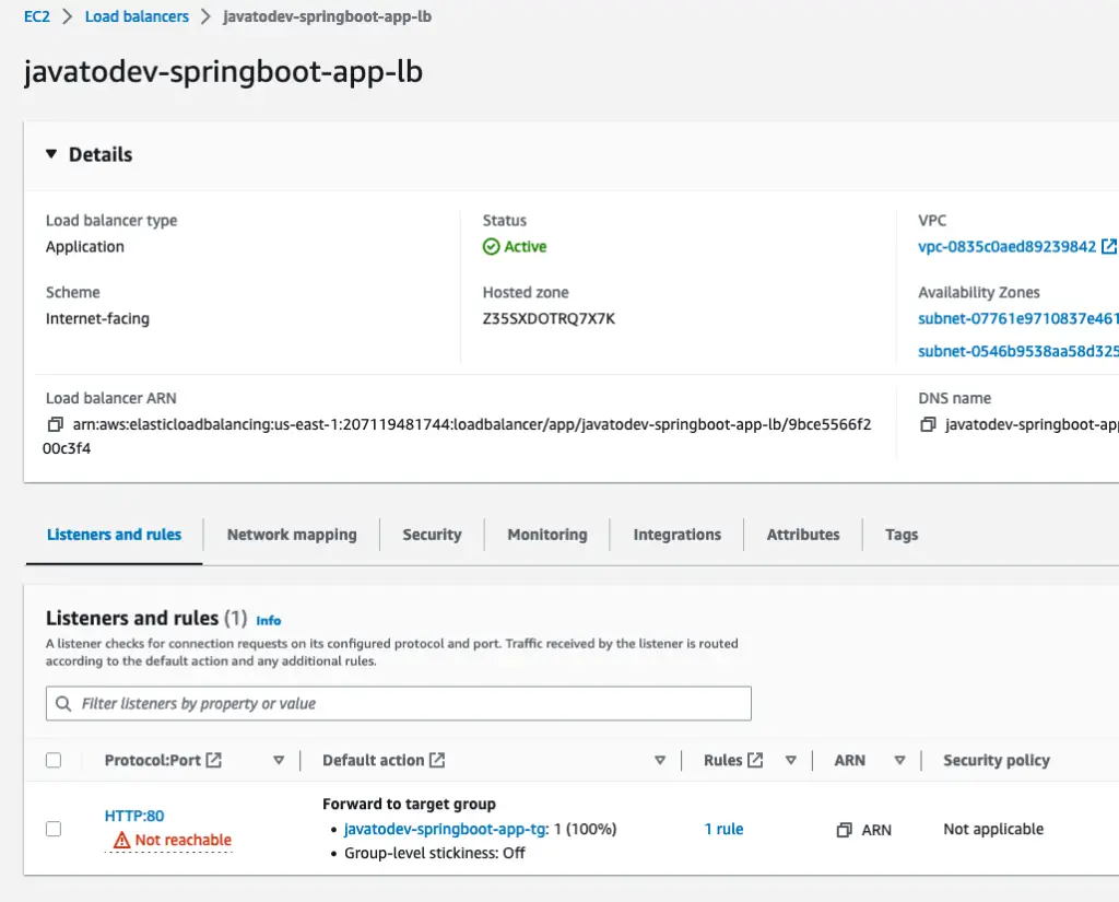
Not reachable target groups for the load balancer
Just move to the load balancer under the EC2 product and change the load balancer subnets to public and set the security group to the javatodev-ecs-app-lb-sg as per the initial plan.
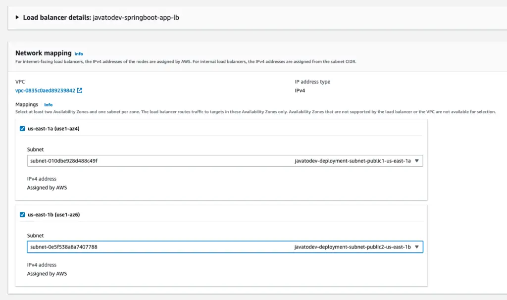
Change subnets public from private subnets for the load balancer
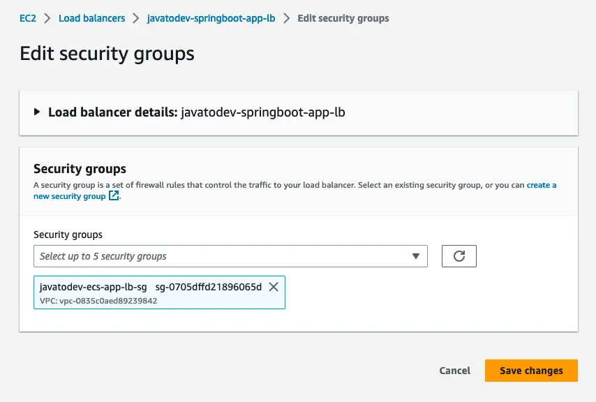
Edit security groups and set the correct load balancer security group
This change might take a few minutes to get effected and you will see all the components created and registered as health targets under the target group.
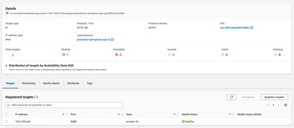
Services are up and running with Healthy targets under the load balancer
Finally, the ECS fargate deployment was completed successfully.
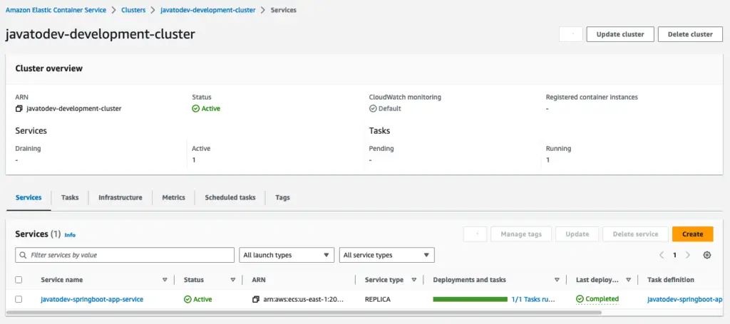
Service deployment completed on ECS fargate
Accessing API With Public API Endpoint
Since we have deployed the necessary services with the load balancer, we can use the load balancer public DNS to access the API. You can find it under load balancer details.
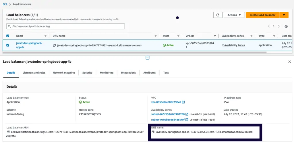
Load Balancer Details page under EC2
We are using a Postman collection to test this API setup. You can sync the Postman collection with this link.
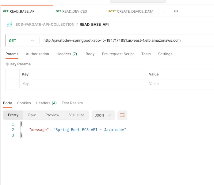
Testing base API path with Postman
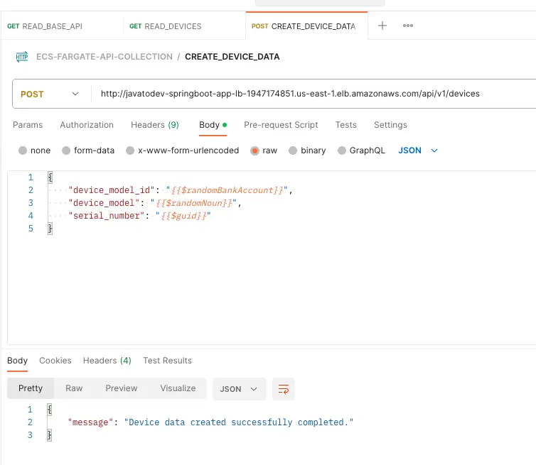
Create device data API testing
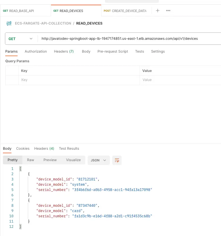
Read device data API with postman
All done, now we have deployed the spring boot application with Amazon ECS and exposed it with load balanced environment to the public.
Conclusion
We are done with setting up the whole architecture on the Amazon ECS cluster in this article series.
Now we can focus on the next step which focuses on Pointing Route 53 Domain To The Application Load Balancer in our next article.
